Rerun comes with built-in support for modeling spatial relationships between entities. This page details how the different archetypes involved interact with each other and explains how transforms are set up in Rerun.
Transforms
Entity path transforms
The Transform3D archetype allows you to specify how one coordinate system relates to another through translation, rotation, and scaling.
The simplest way to use transforms is through entity path hierarchies, where each transform describes the relationship between an entity and its parent path. Note that by default, all entities are connected via identity transforms.
"""Logs a simple transform hierarchy."""

import rerun as rr

rr.init("rerun_example_transform3d_hierarchy_simple", spawn=True)

# Log entities at their hierarchy positions.
rr.log(
    "sun",
    rr.Ellipsoids3D(
        half_sizes=[1, 1, 1], colors=[255, 200, 10], fill_mode="solid"
    ),
)
rr.log(
    "sun/planet",
    rr.Ellipsoids3D(
        half_sizes=[0.4, 0.4, 0.4], colors=[40, 80, 200], fill_mode="solid"
    ),
)
rr.log(
    "sun/planet/moon",
    rr.Ellipsoids3D(
        half_sizes=[0.15, 0.15, 0.15], colors=[180, 180, 180], fill_mode="solid"
    ),
)

# Define transforms - each describes the relationship to its parent.
rr.log(
    "sun/planet", rr.Transform3D(translation=[6.0, 0.0, 0.0])
)  # Planet 6 units from sun.
rr.log(
    "sun/planet/moon", rr.Transform3D(translation=[3.0, 0.0, 0.0])
)  # Moon 3 units from planet.
In this hierarchy:
- The
sunentity exists at the origin of its own coordinate system - The
sun/planettransform places the planet 6 units from the sun, along the x-axis - The
sun/planet/moontransform places the moon 3 units along x away from the planet
This creates a transform hierarchy where transforms propagate down the entity tree. The moon's final position in the sun's coordinate system is 9 units away (6 + 3), because the transforms are applied sequentially.
Named transform frames
While entity path hierarchies work well for many cases, sometimes you need more flexibility in organizing your transforms. In particular, for anyone familiar with ROS, we recommend using named transform frames as it allows you to model your data much closer to how it would be defined when using ROS' tf2 library.
By explicitly specifying transform frames, you can decouple spatial relationships from the entity hierarchy.
Instead of relying on entity path relationships, each entity is first associated with a named transform frame using
the CoordinateFrame archetype.
The geometric relationship between two transform frames is then determined by logging Transform3D
with child_frame and parent_frame parameters set to their respective names.
"""Logs a simple transform hierarchy with named frames."""

import rerun as rr

rr.init("rerun_example_transform3d_hierarchy_named_frames", spawn=True)

# Define entities with explicit coordinate frames.
rr.log(
    "sun",
    rr.Ellipsoids3D(
        half_sizes=[1, 1, 1], colors=[255, 200, 10], fill_mode="solid"
    ),
    rr.CoordinateFrame("sun_frame"),
)
rr.log(
    "planet",
    rr.Ellipsoids3D(
        half_sizes=[0.4, 0.4, 0.4], colors=[40, 80, 200], fill_mode="solid"
    ),
    rr.CoordinateFrame("planet_frame"),
)
rr.log(
    "moon",
    rr.Ellipsoids3D(
        half_sizes=[0.15, 0.15, 0.15], colors=[180, 180, 180], fill_mode="solid"
    ),
    rr.CoordinateFrame("moon_frame"),
)

# Define explicit frame relationships.
rr.log(
    "planet_transform",
    rr.Transform3D(
        translation=[6.0, 0.0, 0.0],
        child_frame="planet_frame",
        parent_frame="sun_frame",
    ),
)
rr.log(
    "moon_transform",
    rr.Transform3D(
        translation=[3.0, 0.0, 0.0],
        child_frame="moon_frame",
        parent_frame="planet_frame",
    ),
)

# Connect the viewer to the sun's coordinate frame.
# This is only needed in the absence of blueprints since a default view will
# typically be created at `/`.
rr.log("/", rr.CoordinateFrame("sun_frame"), static=True)
Note that unlike in ROS, you can log your transform relationship on any entity.
Named transform frames have several advantages over entity path based hierarchies:
- topology may change over time
- association of entities with coordinate frames is explicit and may changed over time (it can also be overridden via blueprint)
- several entities may be associated with the same frame
- frees up entity paths for semantic rather than geometric organization
One parent per frame
A transform frame has exactly one parent at any point in time. This is the same convention that ROS' tf2 uses.
A transform relationship is identified by its child_frame.
Logging another Transform3D with the same child_frame but a different parent_frame therefore does not add a second relationship, it replaces the existing one:
rr.log("tf", rr.Transform3D(parent_frame="first_parent", child_frame="child"))
rr.log("tf", rr.Transform3D(parent_frame="second_parent", child_frame="child"))
Both calls are part of the recording. child has first_parent as its parent up to the second call, and second_parent from there on.
Since transforms are resolved for a single point in time, first_parent and child end up unrelated as soon as the time cursor is past the second call.
This structure can make expressing a transform with two natural parents a bit unintuitive. Typically, it is best to invert one of the two relationships instead and use relation=ChildFromParent:
rr.log("tf", rr.Transform3D(parent_frame="first_parent", child_frame="child"))
# Same values as the `second_parent` to `child` transform, expressed as `child` to `second_parent`:
rr.log(
    "tf",
    rr.Transform3D(parent_frame="child", child_frame="second_parent", relation=rr.TransformRelation.ChildFromParent),
)
first_parent now stays connected and all three frames can be transformed into each other.
Entity hierarchy based transforms under the hood
Under the hood, Rerun's entity path hierarchies actually use the same transform frame system as named frames.
For each entity path, an associated transform frame with the prefix tf# is automatically created:
for example, an entity /world/robot gets frame tf#/world/robot.
Path based hierarchies are then established by defaults the Viewer uses (also referred to as fallbacks):
Given an entity /world/robot:
- if no
CoordinateFrame::frameis specified, it automatically defaults totf#/world/robot - if no
Transform3D::child_frameis specified, it automatically defaults totf#/world/robot - if no
Transform3D::parent_frameis specified, it automatically defaults to the parent's implicit frame,tf#/world
The only special properties these implicit frames have over their named counterparts is that they have implicit identity relationships.
Example
Given these entities:
rr.log("robot", rr.Transform3D(translation=[1, 0, 0]))
rr.log("robot/arm", rr.Transform3D(translation=[0, 1, 0]))
rr.log("robot/arm/gripper", rr.Points3D([0, 0, 0]))
Rerun will interpret this as-if it was logged with the named transform frames like so:
rr.log(
    "robot",
    rr.CoordinateFrame("tf#/robot"),
    rr.Transform3D(translation=[1, 0, 0], child_frame="tf#/robot", parent_frame="tf#/"),
)
rr.log(
    "robot/arm",
    rr.CoordinateFrame("tf#/robot/arm"),
    rr.Transform3D(translation=[0, 1, 0], child_frame="tf#/robot/arm", parent_frame="tf#/robot"),
)
rr.log("robot/arm/gripper", rr.CoordinateFrame("tf#/robot/arm/gripper"), rr.Points3D([0, 0, 0]))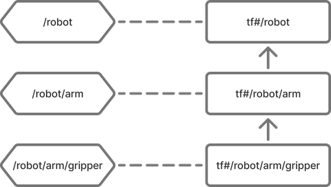
Mixing named and implicit transform frames
We generally do not recommend mixing named and implicit transform frames since it can get confusing, but doing so works seamlessly and can be useful if necessary.
Example:
rr.log("robot", rr.Transform3D(translation=[1, 0, 0]))
rr.log(
    "arm",
    rr.Transform3D(translation=[0, 1, 0], parent_frame="tf#/robot", child_frame="arm_frame"),
    rr.CoordinateFrame("arm_frame"),
)
rr.log("gripper", rr.Points3D([0, 0, 0]), rr.CoordinateFrame("arm_frame"))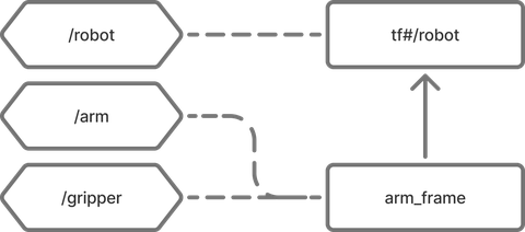
Other transform types
Pinhole projections
In Rerun, pinhole cameras are not merely another archetype that can be visualized, they are also treated as spatial relationships that define projections from 3D spaces to 2D subspaces. This unified approach allows the Viewer to handle both traditional 3D-to-3D transforms and 3D-to-2D projections.
The Pinhole archetype defines this projection relationship through its intrinsic matrix (image_from_camera) and resolution.
Both implicit & named coordinate frames are supported, exactly as on Transform3D.
With the right setup, pinholes allow a bunch of powerful visualizations:
- the pinhole glyph itself in 3D views
- 2D in 3D: all 2D content that is part of the pinhole's transform subtree
- 3D in 2D: if the pinhole is at the origin of the view, 3D objects can be projected through pinhole camera into the view.
A transform frame relationship can have both a Pinhole and a regular Transform3D (in this context often regarded as the camera extrinsics).
Both are used: the Transform3D places the camera in the parent space, and the Pinhole projects from the camera's 3D space onto the 2D image.
So when going from the parent 3D space to the image, the regular transform is applied first, then the projection.
Sizing the frustum
The Pinhole archetype has three fields that only change how the camera looks in 3D views:
image_plane_distance: how far from the camera origin the image plane (and thus the frustum) is drawn. It does not affect the projection. By default, it is derived from the size of the scene.color: the color of the frustum wireframe.line_width: the width of the frustum wireframe lines.
rr.log(
    "world/camera",
    rr.Pinhole(focal_length=500, width=640, height=480, image_plane_distance=0.5, color=[255, 128, 0], line_width=0.01),
)
You can also set these for all cameras in a view with a view default, e.g. rrb.Spatial3DView(defaults=[rr.Pinhole.from_fields(image_plane_distance=0.5)]).
A DepthImage logged under a pinhole entity is back-projected into a 3D point cloud in 3D views, using the pinhole's intrinsics.
Example: 3D scene with 2D projections
Here's how to set up a 3D scene with pinhole cameras that create 2D projections:
In this example, the 3D objects (box and points) are automatically projected into the 2D camera view, demonstrating how Rerun's transform system handles the spatial relationship between 3D world coordinates and 2D image coordinates through pinhole projections.
"""Demonstrates pinhole camera projections with Rerun blueprints."""

import numpy as np

import rerun as rr
import rerun.blueprint as rrb

rr.init("rerun_example_pinhole_projections", spawn=True)

img_height, img_width = 12, 16

# Create a 3D scene with a camera and an image.
rr.log(
    "world/box",
    rr.Boxes3D(centers=[0, 0, 0], half_sizes=[1, 1, 1], colors=[255, 0, 0]),
)
rr.log(
    "world/points",
    rr.Points3D(
        positions=[(1, 0, 0), (-1, 0, 0), (0, 1, 0), (0, -1, 0), (0, 0, 1)],
        colors=[
            (255, 0, 0),
            (0, 255, 0),
            (0, 0, 255),
            (255, 255, 0),
            (255, 0, 255),
        ],
        radii=0.1,
    ),
)
rr.log(
    "camera",
    rr.Transform3D(translation=[0, 3, 0]),
    rr.Pinhole(
        width=img_width,
        height=img_height,
        focal_length=10,
        camera_xyz=rr.ViewCoordinates.LEFT_HAND_Z_UP,
    ),
)
# Create a simple test image.
checkerboard = np.zeros((img_height, img_width, 1), dtype=np.uint8)
checkerboard[
    (np.arange(img_height)[:, None] + np.arange(img_width)) % 2 == 0
] = 255
rr.log("camera/image", rr.Image(checkerboard))

# Use a blueprint to show both 3D and 2D views side by side.
blueprint = rrb.Blueprint(
    rrb.Horizontal(
        # 3D view showing the scene and camera
        rrb.Spatial3DView(
            origin="world",
            name="3D Scene",
            contents=["/**"],
            overrides={
                # Adjust visual size of camera frustum in 3D view for
                # better visibility.
                "camera": rr.Pinhole.from_fields(image_plane_distance=1.0)
            },
        ),
        # 2D projection from angled camera
        rrb.Spatial2DView(
            # Make sure that the origin is at the camera's path.
            origin="camera",
            name="Camera",
            contents=["/**"],  # Add everything, so 3D objects get projected.
        ),
    )
)

rr.send_blueprint(blueprint)

View coordinates
ViewCoordinates describes an orientation convention by specifying the directions in which the positive X, Y, and Z axes point.
It controls camera and view orientation.
For a 3D view, SpatialInformation.axes controls the eye orientation, navigation, and default grid plane.
A logged ViewCoordinates archetype provides the default value for 3D views whose origin is at or below that entity.
The view uses the value at its origin or the closest ancestor, so logging rr.log("/", rr.ViewCoordinates.RIGHT_HAND_Z_UP, static=True) applies to all 3D views unless a view overrides it in its blueprint.
If no archetype value is found, the view uses camera_xyz from the closest ancestor pinhole, followed by RFU as the final fallback.
This orientation does not change logged transforms.
For a Pinhole, camera_xyz controls the camera orientation and projection direction.
The default is RDF: +X is right, +Y is down, and +Z is forward.
Changing camera_xyz reorients the camera frustum, projected depth data, and the projection of 3D content into the camera view.
See the open_photogrammetry_format example for a non-default camera orientation.
For 2D spaces and other entities, view coordinates currently have currently no effect (#1387).
Pose transforms
InstancePoses3D defines geometric poses relative to an entity's transform frame.
Unlike with Transform3D, poses do not propagate through the transform hierarchy
and can store an arbitrary amount of transforms on the same entity.
For an entity that has both Transform3D
(without child_frame/parent_frame) and InstancePoses3D,
the Transform3D is applied first
(affecting the entity and all its children), then InstancePoses3D
is applied only to that specific entity.
(This is consistent with how entity hierarchy based transforms translate to transform frames.)
Instancing
Rerun's InstancePoses3D archetype is not only used
to model poses relative to an Entity's frame, but also for repeating (known as "instancing") visualizations on the same entity:
most visualizations will show once for each transform on InstancePoses3D
in the respective place.
"""
Log a simple 3D mesh with several instance pose transforms.

This instantiate the mesh several times and will not
affect its children. This is known as mesh instancing.
"""

import rerun as rr

rr.init("rerun_example_mesh3d_instancing", spawn=True)
rr.set_time("frame", sequence=0)

rr.log(
    "shape",
    rr.Mesh3D(
        vertex_positions=[[1, 1, 1], [-1, -1, 1], [-1, 1, -1], [1, -1, -1]],
        triangle_indices=[[0, 2, 1], [0, 3, 1], [0, 3, 2], [1, 3, 2]],
        vertex_colors=[[255, 0, 0], [0, 255, 0], [0, 0, 255], [255, 255, 0]],
    ),
)
# This box will not be affected by its parent's instance poses!
rr.log(
    "shape/box",
    rr.Boxes3D(half_sizes=[[5.0, 5.0, 5.0]]),
)

for i in range(100):
    rr.set_time("frame", sequence=i)
    rr.log(
        "shape",
        rr.InstancePoses3D(
            translations=[[2, 0, 0], [0, 2, 0], [0, -2, 0], [-2, 0, 0]],
            rotation_axis_angles=rr.RotationAxisAngle(
                [0, 0, 1], rr.Angle(deg=i * 2)
            ),
        ),
    )

In this example, the mesh at "shape" is instantiated four times with different translations and rotations.
The box at "shape/box" is not affected by its parent's instance poses and appears only once.
Rotation conventions and precision
- Quaternions are
xyzw, with the scalar last:rr.Quaternion(xyzw=[x, y, z, w]). Libraries such as Eigen or ROS messages may store them in a different order, so check before passing them on. - There are no Euler angles.
Convert them yourself, e.g. with
scipy.spatial.transform.Rotation.from_euler("xyz", angles).as_quat()(which also returnsxyzw). You can also userr.RotationAxisAngle(axis=…, degrees=…)or a 3×3 matrix (mat3x3). - Order of operations: the components of
Transform3Dare applied in the reverse order they are listed:mat3x3first, thenscale, then the rotation, thentranslation. - Transforms are 32-bit floats.
All transform values (translation, rotation, scale, and matrices) are stored as
Float32, so 64-bit values are converted when logged. Very large coordinates, such as GPS or UTM positions, lose precision and can make the scene jitter. Subtract a local origin before logging so the values stay small. 64-bit transforms are not supported yet.
Visualizing transforms
In 3D views, a transform can be shown as three axis arrows (red, green, and blue for X, Y, and Z).
The arrows are shown when the entity has a
TransformAxes3Darchetype, and automatically for entities with aPinhole. ATransform3Dalone shows no arrows. To show them, logTransformAxes3Don the same entity:rr.log("robot/arm", rr.Transform3D(translation=[0, 1, 0]), rr.TransformAxes3D(axis_length=0.5))axis_lengthsets the arrow length, in the local units of the transform. You can also set it with a blueprint override or view default.To hide the arrows, select the entity and remove the
TransformAxes3Dvisualizer in the selection panel.To show axes at the origin of the 3D view itself, set
show_axeson the view:rrb.Spatial3DView(spatial_information=rrb.SpatialInformation(show_axes=True)).
Reading transforms back
There is no SDK API that resolves the final pose of an entity in the world (the composition of all transforms up the tree).
You can:
- Query the logged
Transform3D(andPinhole) columns with the dataframe API, and compose the transforms yourself. - Ask a running Viewer with the experimental
rerun.experimental.ViewerClient.get_transform_graph(). It returns the frames and the latest direct parent-child edges at the Viewer's current time, not composed world poses. Passinclude_transforms=Trueto get the transform values.
Debugging transform trees
The Rerun viewer features a debugging UI for visual introspection of the 3D transform cache. This allows to view the tree structure of the transforms, including potentially disconnected trees, and inspect the latest stored values of each frame node or transform edge. The UI supports horizontal and vertical tree layout and you can filter by transform type (e.g. static or temporal).
Agents can also inspect the transform graph through the Viewer's MCP server using rerun_get_transform_graph.
The tool provides a machine-readable JSON snapshot of the transform graph, including frame connections and optional transform values.